CUSTOMIZATION SERVICE PROCESS
Provide customization services according to different working conditions


The filter has good filtering effect and high precision,but it is difficult to clean after blocking, so must be replaced.
The filter element adopts imported glass fiber filter material,which has the advantages of high filtration
precision,strong oil passing capacity,small original pressure and large pollutant holding capacity.The filtration accuracy is calibrated with absolute filtration accuracy,and its filtration ratio β 3,5,10,20≥200,filtration
efficiency n≥99.5%.Comply with ISO standards.
| Model | drift diameter (mm) |
Flow rate (L/min) |
filtration accuracy (μm) |
nominal pressure (MPa) |
pressure loss (MPa) |
transmitter power | weight (Kg) |
Model of element | Connect | |
|---|---|---|---|---|---|---|---|---|---|---|
| Initia | Max | |||||||||
| ZU/QU-H10x*P | 15 | 10 | 1 3 5 10 20 30 |
32 | 0.08 | 0.35 | 24V/48W 220V/50W |
3.6 | HX - 10 X * # | tubular |
| ZU/QU-H25x*P | 25 | 5.0 | HX - 25 x * # | |||||||
| ZU/QU-H40X*P | 20 | 40 | 0.1 | 8.0 | HX - 40 X * # | |||||
| ZU/QU-H63x*P | 63 | 9.8 | HX — 63 x * # | |||||||
| ZU/QU-H100x*P | 25 | 100 | 12.0 | HX - 100 X * # | ||||||
| ZU/QU-H160x*P | 32 | 160 | 0.12 | 18.2 | HX - 160 X * # | |||||
| ZU/QU-H250X*FP | 40 | 250 | 23.0 | HX - 250 x * # | flange type | |||||
| ZU/QU-H400x*FP | 50 | 400 | 0.15 | 133.8 | HX - 400 X * # | |||||
| ZU/QU-H630x*FP | 53 | 630 | 42.0 | HX - 630 X * # | ||||||
| ZU/QU-H800x*FP | 800 | 52.0 | HX - 800 X * # | |||||||
Note:*refers to the filtration accuracy, # refers to the filter material. If the medium used is water glycol,the operating pressure is 32Mpa,the nominal flow is 63L/min,the filter material is paper,with transmitter and by-pass valve,the filter model is Zui Bh-h63x*P, filter element model is HX BH-63X*Q.If the filter material is chemical fiber with transmitter,the filter model is qu.bh-63x*Q and the filter element model is HX Bh-63x*Q,the filter material is metal mesh with transmitter,then the filter model is wu-h63x*P and the filter element model is HX - 63x*W.
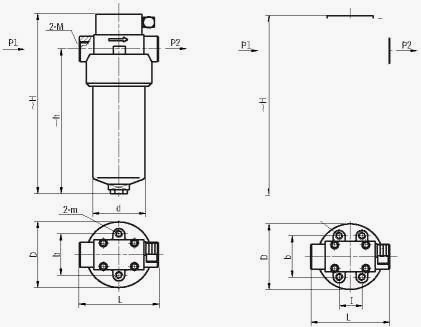
Table I. tubular
| Model | Size (mm) | ||||||||
|---|---|---|---|---|---|---|---|---|---|
| ~H | ~h | L | I | b | D | d | m | M | |
| ZU/QU-H10x*P | 198 | 140 | 118 | 70 | Φ88 | Φ73 | 2-M6 | M27x2 | |
| ZU/QU-H25x*P | 288 | 230 | |||||||
| ZU/QU-H40x*P | 255 | 194 | 128 | 44 | 86 | Φ124 | Φ102 | 4-M10 | M33X2 |
| ZU/QU-H63x*P | 323 | 262 | |||||||
| ZU/QU-H100x*P | 394 | 329 | M42x2 | ||||||
| ZU/QU —h160x*p | 435 | 362 | 166 | 60 | 100 | Φ146 | Φ121 | M48X2 | |
Table II flange type
| Model | Size (mm) | ||||||||
|---|---|---|---|---|---|---|---|---|---|
| ~H | ~h | L | I | b | D | d | d1 | m | |
| ZU/QU-H250x*FP | 508 | 430 | 166 | 60 | 100 | 146 | 121 | Φ40 | M10 |
| ZU/QU-H400x*FP | 545 | 461 | 206 | 123 | 170 | 146 | Φ50 | M12 | |
| ZU/QU-H630 x*FP | 647 | 563 | Φ55 | ||||||
| ZU/QU-H800x*FP | 767 | 683 | |||||||
Table III. Plate
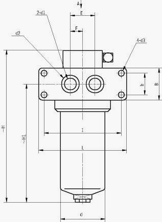
Note: GB/T70.1-2000 12.9 grade screws are recommended for installation
| Model | Size (mm) | |||||||||||||||
|---|---|---|---|---|---|---|---|---|---|---|---|---|---|---|---|---|
| ~H | ~H1 | R | d | L | B | I | b | E | f | h | h1 | h2 | d1 | d2 | d3 | |
| ZU/QU-H10x*BP | 210 | 142 | 46 | Φ73 | 158 | 60 | 128 | 30 | 40 | 20 | 50 | 110 | 22 | Φ15 | Φ24 | Φ13 |
| ZU/QU-H25 x *BP | 300 | 232 | ||||||||||||||
| ZU/QU-H40 x *BP | 269 | 199 | 62 | Φ102 | 190 | 64 | 160 | 32 | 50 | 25 | 65 | 138 | 25 | Φ25 | Φ32 | Φ15 |
| ZU/QU-H63x*BP | 337 | 267 | ||||||||||||||
| ZU/QU-H100x*BP | 399 | 329 | ||||||||||||||
| ZU/QU-H160x*BP | 426 | 353 | 73 | Φ121 | 212 | 72 | 180 | 40 | 60 | 30 | 77 | 164 | 30 | Φ32 | Φ40 | Φ17 |
| ZU/QU-H250x*BP | 507 | 429 | 80 | 48 | 30 | Φ40 | Φ50 | |||||||||
| ZU/QU-H400x*BP | 554 | 461 | 85 | Φ146 | 275 | 110 | 225 | 60 | 80 | 40 | 92 | 194 | 40 | Φ50 | Φ65 | Φ26 |
| ZU/QU-H630 x*BP | 654 | 561 | ||||||||||||||
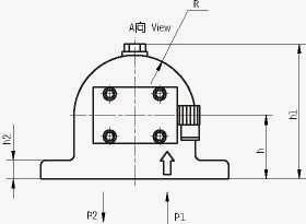
Table IV. inverted tubular
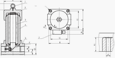
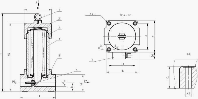
1、eyebolt 2、top cover 3、filter element 4、shell 5、filter head 6、by-pass valve 7、transmitter
| Model | Size (mm) | ||||||||||
|---|---|---|---|---|---|---|---|---|---|---|---|
| H | H1 | L | L1 | B | d1 | h | h1 | h2 | M | d | |
| ZU/QU-H10x*DLP | 198 | 148 | 130 | 95 | 115 | Φ9 | 27.5 | 33 | 54 | M27x2 | Φ92 |
| ZU/QU-H25x*DLP | 288 | 238 | |||||||||
| ZU/QU-H40x*DLP | 247 | 197 | 156 | 115 | 145 | Φ14 | 34 | 41 | 68 | M33x2 | Φ124 |
| ZU/QU-H63x*DLP | 315 | 265 | |||||||||
| ZU/QU-H100x*DLP | 377 | 327 | M42x2 | ||||||||
| ZU/QU-H160x*DLP | 415 | 365 | 190 | 140 | 170 | 46 | 50 | 92 | M48x2 | Φ146 | |
Table v. inverted flange type
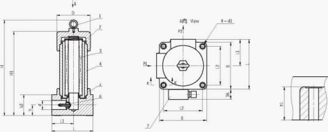
1、eyebolt 2、top cover 3、filter element 4、shell 5、filter head 6、by-pass valve 7、transmitter
| Model | Size (mm) | ||||||||||
|---|---|---|---|---|---|---|---|---|---|---|---|
| H | H1 | D | L | L1 | B | d1 | h | h1 | h2 | d | |
| ZU/QU-H10X*DFP | 198 | 148 | Φ92 | 130 | 95 | 115 | Φ9 | 27.5 | 33 | 54 | Φ18 |
| ZU/QU-H25x*DFP | 288 | 238 | |||||||||
| ZU/QU-H40x*DFP | 247 | 197 | Φ124 | 156 | 115 | 145 | Φ14 | 34 | 41 | 68 | Φ25 |
| ZU/QU-H63x*DFP | 315 | 265 | |||||||||
| ZU/QU-H100x*DFP | 377 | 327 | |||||||||
| ZU/QU-H160x*DFP | 415 | 365 | Φ146 | 190 | 140 | 170 | 46 | 50 | 92 | Φ32 | |
| ZU/QU-H250x*DFP | 485 | 435 | Φ40 | ||||||||
| ZU/QU-H400x*DFP | 532 | 482 | Φ176 | 240 | 160 | 200 | Φ18 | 63 | 75 | 122 | Φ50 |
| ZU/QU-H630 x*DFP | 632 | 582 | Φ55 | ||||||||
| ZU/QU-H800x*DFP | 752 | 702 | |||||||||
Table VI. inverted flange type A
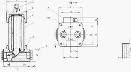
1、eyebolt 2、top cover 3、filter element 4、shell 5、filter head 6、by-pass valve 7、transmitter
| Model | Size (mm) | |||||||||||
|---|---|---|---|---|---|---|---|---|---|---|---|---|
| H | H1 | L | L1 | L2 | B | d1 | h | h1 | h2 | d | D | |
| ZU/QU-H10x* DFAP | 198 | 148 | 122.5 | 65 | 95 | 115 | Φ9 | 27.5 | 33 | 54 | Φ18 | Φ92 |
| ZU/QU-H25X* DFAP | 288 | 238 | ||||||||||
| ZU/QU-H40x* DFAP | 247 | 197 | 150.5 | 78 | 115 | 145 | Φ14 | 34 | 41 | 68 | Φ25 | Φ124 |
| ZU/QU-H63X* DFAP | 315 | 265 | ||||||||||
| ZU/QU-H100X* DFAP | 377 | 327 | ||||||||||
| ZU/QU-H160X* DFAP | 415 | 365 | 180 | 95 | 140 | 170 | 46 | 50 | 92 | Φ32 | Φ146 | |
| ZU/QU-H250X* DFAP | 485 | 435 | Φ40 | |||||||||
| ZU/QU-H400X* DFAP | 532 | 482 | 220 | 120 | 160 | 200 | Φ18 | 63 | 75 | 122 | Φ50 | Φ176 |
| ZU/QU-H630X* DFAP | 632 | 582 | Φ55 | |||||||||
| ZU/QU-H800X* DFAP | 752 | 702 | ||||||||||
Table VII. Inverted flange type B
1、eyebolt 2、top cover 3、filter element 4、shell 5、filter head 6、by-pass valve 7、transmitter
| Model | Size (mm) | |||||||||||
|---|---|---|---|---|---|---|---|---|---|---|---|---|
| H | H1 | L | L1 | L2 | B | d1 | h | h1 | h2 | d | D | |
| ZU/QU-H10x* DFBP | 198 | 148 | 122.5 | 65 | 95 | 115 | Φ9 | 27.5 | 33 | 54 | Φ18 | Φ92 |
| ZU/QU-H25X* DFBP | 288 | 238 | ||||||||||
| ZU/QU-H40x* DFBP | 247 | 197 | 150.5 | 78 | 115 | 145 | Φ14 | 34 | 41 | 68 | Φ25 | Φ124 |
| ZU/QU-H63X* DFBP | 315 | 265 | ||||||||||
| ZU/QU-H100X* DFBP | 377 | 327 | ||||||||||
| ZU/QU-H160X* DFBP | 415 | 365 | 180 | 95 | 140 | 170 | 46 | 50 | 92 | Φ32 | Φ146 | |
| ZU/QU-H250X* DFBP | 485 | 435 | Φ40 | |||||||||
| ZU/QU-H400X* DFBP | 532 | 482 | 220 | 120 | 160 | 200 | Φ18 | 63 | 75 | 122 | Φ50 | Φ176 |
| ZU/QU-H630X* DFBP | 632 | 582 | Φ55 | |||||||||
| ZU/QU-H800X* DFBP | 752 | 702 | ||||||||||
Table VIII. Inverted plate
1、eyebolt 2、top cover 3、filter element 4、shell 5、filter head 6、by-pass valve 7、transmitter
| Model | Size (mm) | ||||||||||||
|---|---|---|---|---|---|---|---|---|---|---|---|---|---|
| H | H1 | D | L | L1 | B | d1 | E | h1 | h2 | d3 | d4 | b | |
| ZU/QU-H10X* BDP | 196 | 146 | Φ92 | 130 | 90 | 115 | Φ11.5 | 60 | 31 | 50 | Φ15 | Φ24 | 14 |
| ZU/QU-H25X*BDP | 286 | 236 | |||||||||||
| ZU/QU-H40X*BDP | 245 | 195 | Φ124 | 156 | 115 | 145 | Φ16 | 88 | 39 | 64 | Φ25 | Φ38 | 15 |
| ZU/QU-H63X*BDP | 313 | 263 | |||||||||||
| ZU/QU-H100X*BDP | 375 | 325 | |||||||||||
| ZU/QU-H160X*BDP | 413 | 363 | Φ146 | 190 | 135 | 170 | Φ18 | 104 | 48 | 88 | Φ40 | Φ50 | 23 |
| ZU/QU-H250X* BDP | 483 | 433 | |||||||||||
| ZU/QU-H400X* BDP | 530 | 480 | Φ176 | 240 | 160 | 200 | Φ26 | 144 | 70 | 118 | Φ50 | Φ65 | 24 |
| ZU/QU-H630X* BDP | 630 | 580 | |||||||||||
| ZU/QU-H800X* BDP | 750 | 700 | |||||||||||
product
video
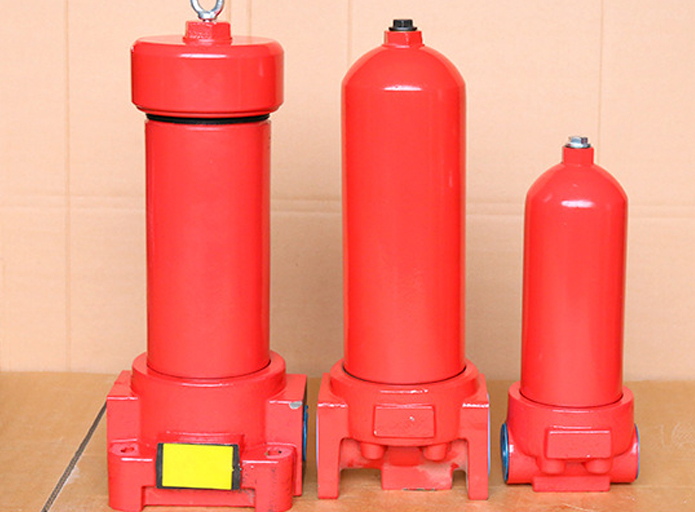
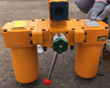
function:hydraulic oil filtrationrate of flow:1000t/h
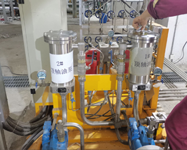
function:hydraulic oil filtrationrate of flow:200t/h
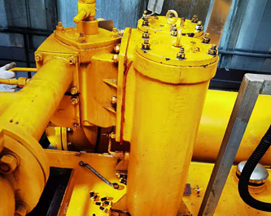
function: oil filtratiionrate of flow:100t/h
Provide customization services according to different working conditions
Professional installation team to ensure the normal operation of the equipment
Technical Support


